At Rapid Enterprises Inc we believe a well-informed client is the best customer. When a client understands how the complexity of design and production setup affects price and timelines a solid partnership is built. Many of our articles include new trends and advances in technology because we are always moving forward to provide the best quality in the least time. Understanding some of these new approaches is made easier when we first go back to CNC basics. Here we review the basic components of a CNC machine.
Overview
Machining starts with a worktable housed in a frame to hold the raw material and introduces cutting tools to remove material to form a finished part. Think of a vice holding something stationary while another tool works on that piece. Computer Numerical Control means that, rather than manual operation, a machine works on commands sent in computer code to move, turn, and cut. Beyond the motor and the housing, the process in manual or automated machining is the same, and the parts that do the work are all based on these definitions.
Rails and Guides – The workpiece needs to be held in place securely on the horizontal work surface. Rails and guides set the parameters for the size of raw material that can be loaded onto the work platform and hold it in place by adjusting and moving various guides to align with the sides of the raw material.
Chuck – When a workpiece has an irregular shape it often can’t be held in place with standard rails and guards. A chuck is a special clamping system that can work manually, pneumatically, hydraulically, or electrically to hold the workpiece. Chucks may hold the outside or inside diameter and have varied clasping approaches depending on the type of CNC machine operation.
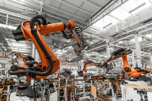
Gantry – A gantry system is a moving bridge, typically above the workpiece, that smoothly moves the cutting tools in place on one or more axes. The height and range of the gantry arm will dictate the size of piece that can be machined.
Axis – One of the main benefits of CNC machining is the multiple-axis approach to cutting operations. The worktable provides the X and Y axis and the cutting tool, most often mounted above, provides the Z-axis in basic CNC machining. The cutting tool can be directed to move along any of these axes to provide basic shape forming. More advanced machines utilize from 5 to 9 axes. This allows multiple angles of approach and eliminates costly machine setups to reset a workpiece for a complicated design.
Coupler – This is the connection between the spindle and the motor. As the name states, it couples the two together and manages the differential in torque between the two shafts.
Spindle – A spindle is a rotating mechanism that drives the cutting tool. This shaft is connected to the motor by a coupler to manage any differential in torque. High-speed spindles may have their own motor and dictate the quality of the machining process. The spindle has a clamping system to hold the cutting tool.
Turret – The tools that cut the raw material stock are held in a turret. Turrets vary in size and the amount of cutting tools they can hold. In a complicated machining operation, many tools may be commanded into action to perform one operation, like a threaded hole. Turrets are designed to precisely hold the cutting tool to minimize vibration and warp.
Machine Tool (Cutting Tool) – The final piece is the cutting tool. Tools vary in material, style, and size to approach the desired application. Cutting tools can drill holes or create threads. They can form rounded edges and add slots, grooves, and tapers to raw material to create just about anything. Tools must be properly mounted and maintained to provide accuracy and avoid breakage.
A variety of designs are available for spindles, chucks, and cutting tools depending on the machining operation. Understanding the hardware helps conceptualize how a machine works to improve the communication between client and manufacturer. The next step back to CNC basics is understanding the software element that moves all these working pieces in harmony to produce a finished part. Watch for our next blog, Part 2 of Back to CNC Basics – The Software, and contact us with any questions you have about understanding the CNC machining process.